<?xml version="1.0" encoding="utf-8"?><feed xmlns="http://www.w3.org/2005/Atom" ><generator uri="https://jekyllrb.com/" version="4.4.1">Jekyll</generator><link href="/feed.xml" rel="self" type="application/atom+xml" /><link href="/" rel="alternate" type="text/html" /><updated>2026-05-08T10:50:52+00:00</updated><id>/feed.xml</id><title type="html">Matt’s Tech Blog</title><subtitle>Mostly a place to document things related to electronics and programming. </subtitle><entry><title type="html">Flashing ESPHome to the Smartmesh 9W CCT Bulb (Part 2)</title><link href="/smartmesh/flashing/riscv/smartbulb/esp32/2026/05/05/smartmesh-bulb-2.html" rel="alternate" type="text/html" title="Flashing ESPHome to the Smartmesh 9W CCT Bulb (Part 2)" /><published>2026-05-05T17:58:41+00:00</published><updated>2026-05-05T17:58:41+00:00</updated><id>/smartmesh/flashing/riscv/smartbulb/esp32/2026/05/05/smartmesh-bulb-2</id><content type="html" xml:base="/smartmesh/flashing/riscv/smartbulb/esp32/2026/05/05/smartmesh-bulb-2.html"><![CDATA[<p><img src="/images/smartmesh/smartmesh-leds.jpg" alt="the led pcb, with unpopulated RGB pads" /></p>

<p>(Continued from <a href="/smartmesh/riscv/smartbulb/esp32/2026/05/04/smartmesh-bulb-1.html">previous post</a>)</p>

<p>Time to make some changes to the bulb. ESPHome is what I normally use, so I’m going with that.</p>

<p>6 pins in total need to be connected:</p>
<ul>
  <li>two power rails (3.3V),</li>
  <li>the RX and TX pins,</li>
  <li>gpio8 pulled to VCC (for flashing)</li>
  <li>gpio9 to GND (for flashing)</li>
</ul>

<p>I have a little harness board to organize the wires.</p>

<p>Because the flash size is tiny (2MB vs normal 4MB), I had to disable some ESPHome features. There is no fallback portal now, so using the bulb elsewhere on another wifi is going to be tricky.</p>

<p>
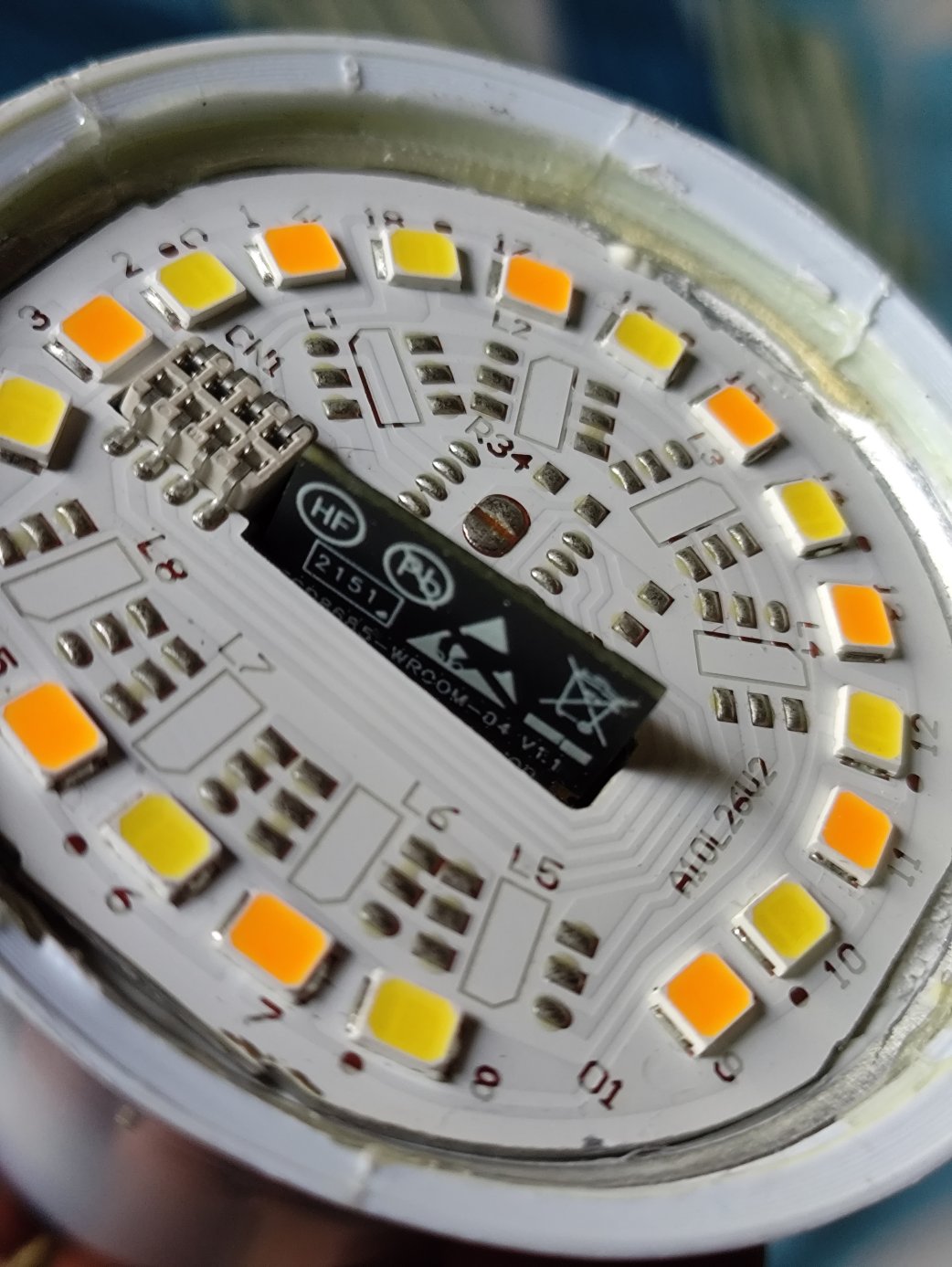
It took some trial and error to get the config right because I didn’t bother tracing the tracks. The BP5936 accepts one PWM channel for brightness, and a second one for color temperature.</p>

<h2 id="final-config">final config</h2>

<div class="language-yaml highlighter-rouge"><div class="highlight"><pre class="highlight"><code><span class="na">esphome</span><span class="pi">:</span>
  <span class="na">name</span><span class="pi">:</span> <span class="s">smartmesh-cct-9w</span>
  <span class="na">friendly_name</span><span class="pi">:</span> <span class="s">smartmesh-cct-9w</span>

<span class="na">esp32</span><span class="pi">:</span>
  <span class="na">board</span><span class="pi">:</span> <span class="s">esp32-c3-devkitm-1</span>
  <span class="na">flash_size</span><span class="pi">:</span> <span class="s">2MB</span>
  <span class="na">framework</span><span class="pi">:</span>
    <span class="na">type</span><span class="pi">:</span> <span class="s">esp-idf</span>

<span class="c1"># Enable logging</span>
<span class="na">logger</span><span class="pi">:</span>
  <span class="na">level</span><span class="pi">:</span> <span class="s">WARN</span>
  
<span class="c1"># Enable Home Assistant API</span>
<span class="na">api</span><span class="pi">:</span>
<span class="c1">#  encryption:</span>
<span class="c1">#    key: "secretkey"</span>

<span class="na">ota</span><span class="pi">:</span>
  <span class="pi">-</span> <span class="na">platform</span><span class="pi">:</span> <span class="s">esphome</span>
    <span class="na">password</span><span class="pi">:</span> <span class="s2">"</span><span class="s">secretpassword"</span>

<span class="na">wifi</span><span class="pi">:</span>
  <span class="na">ssid</span><span class="pi">:</span> <span class="kt">!secret</span> <span class="s">wifi_ssid</span>
  <span class="na">password</span><span class="pi">:</span> <span class="kt">!secret</span> <span class="s">wifi_password</span>

  <span class="c1"># Disable fallback hotspot (captive portal) </span>
  <span class="c1">#ap:</span>
  <span class="c1">#  ssid: "Smartmesh-Cct-9W"</span>
  <span class="c1">#  password: "emergencypassword"</span>

<span class="c1">#captive_portal:</span>
    

<span class="c1"># Light config</span>

<span class="na">output</span><span class="pi">:</span>
  <span class="pi">-</span> <span class="na">platform</span><span class="pi">:</span> <span class="s">ledc</span>
    <span class="na">pin</span><span class="pi">:</span> <span class="s">GPIO3</span>
    <span class="na">id</span><span class="pi">:</span> <span class="s">out_brightness</span>

  <span class="pi">-</span> <span class="na">platform</span><span class="pi">:</span> <span class="s">ledc</span>
    <span class="na">pin</span><span class="pi">:</span> <span class="s">GPIO6</span>
    <span class="na">id</span><span class="pi">:</span> <span class="s">out_temp</span>
    <span class="na">inverted</span><span class="pi">:</span> <span class="kc">true</span>

<span class="na">light</span><span class="pi">:</span>
  <span class="pi">-</span> <span class="na">platform</span><span class="pi">:</span> <span class="s">color_temperature</span>
    <span class="na">name</span><span class="pi">:</span> <span class="s2">"</span><span class="s">Light"</span>
    <span class="na">color_temperature</span><span class="pi">:</span> <span class="s">out_temp</span>
    <span class="na">brightness</span><span class="pi">:</span> <span class="s">out_brightness</span>
    <span class="na">cold_white_color_temperature</span><span class="pi">:</span> <span class="s">6500 K</span>
    <span class="na">warm_white_color_temperature</span><span class="pi">:</span> <span class="s">2700 K</span>
</code></pre></div></div>

<p>My Home Assistant VM (ESPHome as addon) ran out of space installing the RISC V toolchain, so I had to increase the disk’s size to 24GB from 16GB.</p>

<p>Downsides of taking the bulb apart includes the heat sinking no longer glued in properly, so I don’t want to run it at full brightness unless I fix that.</p>]]></content><author><name></name></author><category term="smartmesh" /><category term="flashing" /><category term="riscv" /><category term="smartbulb" /><category term="esp32" /><summary type="html"><![CDATA[]]></summary><media:thumbnail xmlns:media="http://search.yahoo.com/mrss/" url="/images/smartmesh/smartmesh-leds.jpg" /><media:content medium="image" url="/images/smartmesh/smartmesh-leds.jpg" xmlns:media="http://search.yahoo.com/mrss/" /></entry><entry><title type="html">Exploring the Smartmesh 9W CCT Bulb (Part 1)</title><link href="/smartmesh/riscv/smartbulb/esp32/2026/05/04/smartmesh-bulb-1.html" rel="alternate" type="text/html" title="Exploring the Smartmesh 9W CCT Bulb (Part 1)" /><published>2026-05-04T10:00:00+00:00</published><updated>2026-05-04T10:00:00+00:00</updated><id>/smartmesh/riscv/smartbulb/esp32/2026/05/04/smartmesh-bulb-1</id><content type="html" xml:base="/smartmesh/riscv/smartbulb/esp32/2026/05/04/smartmesh-bulb-1.html"><![CDATA[<p><img src="/images/smartmesh/smartmesh-bulb.jpg" alt="the bulb" /></p>

<p>Cheap CCT tunable wifi smart bulb. Bought in Apr 2026 for ₹280 off Amazon.in, although it was manufactured in Oct 2023.</p>

<ul>
  <li>ESP8685-WROOM-04</li>
  <li>32-bit RISC V, 160MHz</li>
  <li>2MB flash (normal modules have 4MB)</li>
  <li>BP5936 dual channel LED driver</li>
  <li>BP2306, seems to be for the power supply</li>
</ul>

<p>First time tinkering with a device that has a RISC-V processor.</p>

<p>As usual, my aim is to make it work fully locally with Home Assistant, no servers in China involved.</p>

<p>I opened it up, took out the board, soldered wires to the wifi module, and powered it with a 3.3V supply.</p>

<h2 id="stock-firmware-serial-output">Stock firmware serial output</h2>

<div class="language-plaintext highlighter-rouge"><div class="highlight"><pre class="highlight"><code>ESP-ROM:esp32c3-api1-20210207
ESP-ROM:esp32c3-api1-20210207
Build:Feb  7 2021
rst:0xf (BROWNOUT_RST),boot:0x9 (SPI_FAST_FLASH_BOOT)
SPIWP:0xee
mode:DIO, clock div:1
load:0x3fcd6100,len:0xc84
load:0x403ce000,len:0x714
load:0x403d0000,len:0x275c
entry 0x403ce000
ESP-ROM:esp32c3-api1-20210207
Build:Feb  7 2021
rst:0xf (BROWNOUT_RST),boot:0x9 (SPI_FAST_FLASH_BOOT)
SPIWP:0xee
mode:DIO, clock div:1
load:0x3fcd6100,len:0xc84
load:0x403ce000,len:0x714
load:0x403d0000,len:0x275c
entry 0x403ce000
ESP-ROM:esp32c3-api1-20210207
Build:Feb  7 2021
rst:0xf (BROWNOUT_RST),boot:0x9 (SPI_FAST_FLASH_BOOT)
SPIWP:0xee
mode:DIO, clock div:1
load:0x3fcd6100,len:0xc84
load:0x403ce000,len:0x714
load:0x403d0000,len:0x275c
entry 0x403ce000
I (38) cpu_start: Pro cpu up.
I (50) cpu_start: Pro cpu start user code
I (50) cpu_start: cpu freq: 160000000
I (50) cpu_start: Application information:
I (50) cpu_start: Project name:     smartbulb
I (54) cpu_start: App version:      eef5c8b-dirty
I (58) cpu_start: Compile time:     Jan 26 2023 11:46:49
I (63) cpu_start: ELF file SHA256:  94d0c934ef33a9a1...
I (68) cpu_start: ESP-IDF:          v4.3
I (72) heap_init: Initializing. RAM available for dynamic allocation:
I (78) heap_init: At 3FC96700 len 00029900 (166 KiB): DRAM
I (83) heap_init: At 3FCC0000 len 0001F060 (124 KiB): STACK/DRAM
I (89) heap_init: At 50000010 len 00001FE0 (7 KiB): RTCRAM
I (95) spi_flash: detected chip: generic
I (98) spi_flash: flash io: dio
I (101) sleep: Configure to isolate all GPIO pins in sleep state
I (107) sleep: Enable automatic switching of GPIO sleep configuration
I (113) cpu_start: Starting scheduler.
</code></pre></div></div>

<h2 id="stock-firmware-esptool-output">Stock firmware esptool output</h2>

<div class="language-plaintext highlighter-rouge"><div class="highlight"><pre class="highlight"><code>esptool.js
Serial port WebSerial VendorID 0x1a86 ProductID 0x7523
Connecting...
Detecting chip type... ESP32-C3
Chip Revision: 3
Chip is ESP8685 (QFN28) (revision v0.3)
Features: Wi-Fi,BLE,Embedded Flash 2MB (TT)
Crystal is 40MHz
MAC: 58:cf:79:74:3d:58
Uploading stub...
Running stub...
Stub running...
Flash ID: 1560eb
</code></pre></div></div>

<p>(continued <a href="/smartmesh/flashing/riscv/smartbulb/esp32/2026/05/05/smartmesh-bulb-2.html">in part 2</a>)</p>]]></content><author><name></name></author><category term="smartmesh" /><category term="riscv" /><category term="smartbulb" /><category term="esp32" /><summary type="html"><![CDATA[]]></summary><media:thumbnail xmlns:media="http://search.yahoo.com/mrss/" url="/images/smartmesh/smartmesh-bulb.jpg" /><media:content medium="image" url="/images/smartmesh/smartmesh-bulb.jpg" xmlns:media="http://search.yahoo.com/mrss/" /></entry><entry><title type="html">OpenWRT on Dlink DSL-2730U C1 (no wifi, no DSL)</title><link href="/router/openwrt/dsl/dlink/2730u/2018/07/28/dlink-dsl-openwrt.html" rel="alternate" type="text/html" title="OpenWRT on Dlink DSL-2730U C1 (no wifi, no DSL)" /><published>2018-07-28T19:10:00+00:00</published><updated>2018-07-28T19:10:00+00:00</updated><id>/router/openwrt/dsl/dlink/2730u/2018/07/28/dlink-dsl-openwrt</id><content type="html" xml:base="/router/openwrt/dsl/dlink/2730u/2018/07/28/dlink-dsl-openwrt.html"><![CDATA[<p>The DSL-2730U was a common DSL modem-router in the heydays of DSL in India, but now that I have moved on to an optical link, I wanted to re-purpose the modem as a router.</p>

<p>Warning: You will no longer have DSL! You might end up with a brick!! There is no wifi yet!!!</p>

<p>The good news is that the modem has a recovery mode which should help recover from most issues. Turn off the modem. Use a pen to hold down the reset button and turn it back on. The power LED should now turn red. You are now in recovery mode.</p>

<p>So these are the steps (roughly) by which I managed to install openwrt on DLink DSL-2730U C1.</p>

<h2 id="1-figure-out-the-platform-and-wifi">1. Figure out the platform and wifi</h2>
<p>Version being C1, SoC is BCM6328 and wifi is BCM4313. ROM is 8MB and RAM 32MB. There is no official OpenWRT support for our model. Too bad.</p>

<h2 id="2-get-the-rom">2. Get the ROM</h2>
<p>Go to the OpenWRT site, downloads, then look for the generic brcm6328 image. The link below is only a suggestion, perhaps a newer version will work as well.</p>

<p>https://downloads.openwrt.org/releases/17.01.4/targets/brcm63xx/generic/</p>

<p>You need the 8MB generic image, it should be named something like:</p>

<div class="language-plaintext highlighter-rouge"><div class="highlight"><pre class="highlight"><code>96328avng-generic-squashfs-cfe-8M.bin
</code></pre></div></div>

<h2 id="3-flash-the-rom">3. Flash the ROM</h2>
<p>Enter recovery mode (hold reset down when you turn it on).</p>

<p>Connect to the computer with an ethernet cable and go to the recovery address at 192.168.1.1.</p>

<p>A simple page loads. Follow instructions to select and flash the previously downloaded rom. This will take a minute. Modem will eventually reboot and you can log into OpenWRT at 192.168.1.1.</p>

<h2 id="4-set-up-routing">4. Set up routing</h2>
<p>a. I set up ethernet port 1 as the wan port. Add a new VLAN in Network&gt;Switch. Turn off port 1 in the existing VLAN and set it to ‘untagged’ in the new one. Set the cpu to tagged in both.</p>

<p>b. Add a new interface in Network&gt;Interfaces. Select the VLAN you just created and select the WAN firewall zone for it. Set up the WAN using the info your ISP gave you, in my case a static ip address.</p>

<p>Now you can connect the device to your regular modem as a router.</p>

<p>Now for the bonus section.</p>

<h2 id="5-try-installing-wifi-drivers-but-probably-a-waste-of-time">5. Try installing WiFi drivers (but probably a waste of time)</h2>

<p>To refresh package list and install the brcmsmac wifi driver:</p>

<div class="language-bash highlighter-rouge"><div class="highlight"><pre class="highlight"><code>opkg update
opkg <span class="nb">install </span>kmod-brcmsmac
rmmod brcmsmac
modprobe brcmsmac
Now to refresh the configuration files:
<span class="nb">rm</span> <span class="nt">-f</span> /etc/config/wireless
wifi config
<span class="nb">cat</span> /etc/config/wireless
</code></pre></div></div>

<p>Hopefully you just saw a wireless interface listed. Now you might want to install WPA security:</p>

<div class="language-bash highlighter-rouge"><div class="highlight"><pre class="highlight"><code>opkg <span class="nb">install </span>wpad-mini
</code></pre></div></div>

<p>For me the wifi module (BCM4313) is detected and configurable but fails to start up due to some issue with suspend. YMMV.</p>]]></content><author><name></name></author><category term="router" /><category term="openwrt" /><category term="dsl" /><category term="dlink" /><category term="2730u" /><summary type="html"><![CDATA[The DSL-2730U was a common DSL modem-router in the heydays of DSL in India, but now that I have moved on to an optical link, I wanted to re-purpose the modem as a router.]]></summary></entry><entry><title type="html">Figuring out a proprietary quadrature encoder from an old Logitech mouse</title><link href="/mouse/logitech/quadrature/encoder/infrared/cp5928am/2016/05/08/logitech-mouse-quadrature.html" rel="alternate" type="text/html" title="Figuring out a proprietary quadrature encoder from an old Logitech mouse" /><published>2016-05-08T18:07:00+00:00</published><updated>2016-05-08T18:07:00+00:00</updated><id>/mouse/logitech/quadrature/encoder/infrared/cp5928am/2016/05/08/logitech-mouse-quadrature</id><content type="html" xml:base="/mouse/logitech/quadrature/encoder/infrared/cp5928am/2016/05/08/logitech-mouse-quadrature.html"><![CDATA[<p>If you needed a quadrature encoder and couldn’t make sense of the three-pin IR receiver component you found when you ripped up an old Logitech mouse, here’s some help.</p>

<p>The receiver chip is likely a custom Logitech chip which uses a single wire interface to communicate with a custom controller. In my case the controller IC is CP5928AM, for either of which a datasheet is nowhere to be found. They be proprietary.</p>

<p>Fortunately, I found a reference to a relevant Logitech patent (<a href="https://patents.google.com/patent/US6552716">US6552716</a>) on Hackaday forums, and while it only explains general operation and doesn’t offer exact timings, (and I don’t own an oscilloscope), a little trial and error has produced working code.</p>

<p>Based on the patent, I found that data can be read as follows:</p>

<ol>
  <li>You’ll need two free I/O pins on your MCU. Connect one each to the IRLED (I’ll call it LED) and the data pin of the receiver (I’ll call it data pin). Use existing wiring to figure out the pins. Start with LED off, and data pin set to INPUT on the MCU.</li>
  <li>Pulse the LED on and then off. This produces a light pulse which changes the state of a couple of SR latches in the receiver to produce an output which you will now read off a parallel-to-serial shifter.</li>
  <li>Change the data pin to OUTPUT and drive the data pin high and then low. Then change it back to INPUT. Now read the data pin. You have your first directional bit.</li>
  <li>Again, change the data pin to OUTPUT and drive the data pin high and then low. Then change it back to INPUT. Now read the data pin. You have your second directional bit.</li>
  <li>Each bit indicates rotation in one direction. If both are 0, there is no movement. If both are 1, then you are not reading data fast enough.</li>
  <li>Repeat steps 2 to 5.</li>
</ol>

<p>Here’s the code I wrote to test it with my Arduino:</p>

<div class="language-cpp highlighter-rouge"><div class="highlight"><pre class="highlight"><code><span class="cm">/*************************************/</span>
<span class="cm">/*  Logitech Quadrature Encoder      */</span>
<span class="cm">/*  Single wire interface            */</span>
<span class="cm">/*  Code based on patent US6552716.  */</span>
<span class="cm">/*************************************/</span>

<span class="c1">// data, IRLED pins</span>
<span class="cp">#define QEDATAPIN 7
#define QELEDPIN 6
</span>
<span class="kt">int</span> <span class="n">qeOld1</span><span class="p">,</span> <span class="n">qeOld2</span><span class="p">,</span> <span class="n">turns</span><span class="o">=</span><span class="mi">0</span><span class="p">,</span> <span class="n">overflows</span><span class="o">=</span><span class="mi">0</span><span class="p">;</span>

<span class="kt">void</span> <span class="nf">setup</span><span class="p">()</span> <span class="p">{</span>
  <span class="n">Serial</span><span class="p">.</span><span class="n">begin</span><span class="p">(</span><span class="mi">115200</span><span class="p">);</span>
  <span class="n">pinMode</span><span class="p">(</span><span class="n">QEDATAPIN</span><span class="p">,</span> <span class="n">INPUT</span><span class="p">);</span>
  <span class="c1">//turn irled off -- high is OFF</span>
  <span class="n">pinMode</span><span class="p">(</span><span class="n">QELEDPIN</span><span class="p">,</span> <span class="n">OUTPUT</span><span class="p">);</span>
  <span class="n">digitalWrite</span><span class="p">(</span><span class="n">QELEDPIN</span><span class="p">,</span> <span class="n">HIGH</span><span class="p">);</span>
  <span class="n">qeOld1</span><span class="o">=</span><span class="n">qeOld2</span><span class="o">=</span><span class="mi">0</span><span class="p">;</span>
<span class="p">}</span>

<span class="c1">//in microseconds, increase if they don't work</span>
<span class="cp">#define QE_SENSOR_PULSEWIDTH 2
#define QE_IRLED_PULSEWIDTH 2
</span>
<span class="kr">inline</span> <span class="kt">void</span> <span class="nf">qeLEDlightPulse</span><span class="p">(){</span>
  <span class="n">digitalWrite</span><span class="p">(</span><span class="n">QELEDPIN</span><span class="p">,</span> <span class="n">LOW</span><span class="p">);</span>
  <span class="n">delayMicroseconds</span><span class="p">(</span><span class="n">QE_IRLED_PULSEWIDTH</span><span class="p">);</span>
  <span class="n">digitalWrite</span><span class="p">(</span><span class="n">QELEDPIN</span><span class="p">,</span> <span class="n">HIGH</span><span class="p">);</span>
<span class="p">}</span>

<span class="kr">inline</span> <span class="n">byte</span> <span class="nf">getQEDataBit</span><span class="p">(){</span>
  <span class="c1">//switch to output mode and</span>
  <span class="c1">//pulse data line high and then low</span>
  <span class="n">delayMicroseconds</span><span class="p">(</span><span class="n">QE_SENSOR_PULSEWIDTH</span><span class="o">/</span><span class="mi">2</span><span class="p">);</span>
  <span class="n">pinMode</span><span class="p">(</span><span class="n">QEDATAPIN</span><span class="p">,</span> <span class="n">OUTPUT</span><span class="p">);</span>
  <span class="n">digitalWrite</span><span class="p">(</span><span class="n">QEDATAPIN</span><span class="p">,</span> <span class="n">HIGH</span><span class="p">);</span>
  <span class="n">delayMicroseconds</span><span class="p">(</span><span class="n">QE_SENSOR_PULSEWIDTH</span><span class="p">);</span>
  <span class="n">digitalWrite</span><span class="p">(</span><span class="n">QEDATAPIN</span><span class="p">,</span> <span class="n">LOW</span><span class="p">);</span>
  <span class="n">delayMicroseconds</span><span class="p">(</span><span class="n">QE_SENSOR_PULSEWIDTH</span><span class="p">);</span>
  <span class="c1">//switch back to input mode and</span>
  <span class="c1">//read data bit</span>
  <span class="n">pinMode</span><span class="p">(</span><span class="n">QEDATAPIN</span><span class="p">,</span> <span class="n">INPUT</span><span class="p">);</span>
  <span class="n">delayMicroseconds</span><span class="p">(</span><span class="n">QE_SENSOR_PULSEWIDTH</span><span class="p">);</span>
  <span class="k">return</span> <span class="n">digitalRead</span><span class="p">(</span><span class="n">QEDATAPIN</span><span class="p">);</span>
<span class="p">}</span>

<span class="kt">void</span> <span class="nf">loop</span><span class="p">()</span> <span class="p">{</span>
  <span class="n">qeLEDlightPulse</span><span class="p">();</span>
  <span class="n">byte</span> <span class="n">qe1</span> <span class="o">=</span> <span class="n">getQEDataBit</span><span class="p">();</span>
  <span class="n">byte</span> <span class="n">qe2</span> <span class="o">=</span> <span class="n">getQEDataBit</span><span class="p">();</span>
  
  <span class="k">if</span><span class="p">(</span><span class="n">qeOld1</span><span class="o">!=</span><span class="n">qe1</span> <span class="o">||</span> <span class="n">qeOld2</span><span class="o">!=</span><span class="n">qe2</span><span class="p">){</span>
    <span class="k">if</span><span class="p">(</span><span class="n">qe1</span><span class="o">!=</span><span class="mi">0</span><span class="p">)</span>
      <span class="n">turns</span><span class="o">++</span><span class="p">;</span>
    <span class="k">if</span><span class="p">(</span><span class="n">qe2</span><span class="o">!=</span><span class="mi">0</span><span class="p">)</span>
      <span class="n">turns</span><span class="o">--</span><span class="p">;</span>
    <span class="k">if</span><span class="p">(</span><span class="n">qe1</span><span class="o">==</span><span class="n">qe2</span> <span class="o">&amp;&amp;</span> <span class="n">qe1</span><span class="o">==</span><span class="mi">1</span><span class="p">)</span>
      <span class="n">overflows</span><span class="o">++</span><span class="p">;</span>
    <span class="n">Serial</span><span class="p">.</span><span class="n">print</span><span class="p">(</span><span class="n">turns</span><span class="p">);</span>
    <span class="n">Serial</span><span class="p">.</span><span class="n">print</span><span class="p">(</span><span class="s">"</span><span class="se">\t</span><span class="s">-- "</span><span class="p">);</span>
    <span class="n">Serial</span><span class="p">.</span><span class="n">print</span><span class="p">(</span><span class="n">overflows</span><span class="p">);</span>
    <span class="n">Serial</span><span class="p">.</span><span class="n">print</span><span class="p">(</span><span class="s">"</span><span class="se">\t</span><span class="s">-- "</span><span class="p">);</span>
    <span class="n">Serial</span><span class="p">.</span><span class="n">print</span><span class="p">(</span><span class="n">qe1</span><span class="p">);</span>
    <span class="n">Serial</span><span class="p">.</span><span class="n">println</span><span class="p">(</span><span class="n">qe2</span><span class="p">);</span>
  <span class="p">}</span>
  <span class="n">qeOld1</span><span class="o">=</span><span class="n">qe1</span><span class="p">;</span>
  <span class="n">qeOld2</span><span class="o">=</span><span class="n">qe2</span><span class="p">;</span>
<span class="p">}</span>
</code></pre></div></div>]]></content><author><name></name></author><category term="mouse" /><category term="Logitech" /><category term="quadrature" /><category term="encoder" /><category term="infrared" /><category term="CP5928AM" /><summary type="html"><![CDATA[If you needed a quadrature encoder and couldn’t make sense of the three-pin IR receiver component you found when you ripped up an old Logitech mouse, here’s some help.]]></summary></entry></feed>